| |
|
Any logo = HOME
All items stocked
|
Guillen's Enterprises, Inc.
Your place for:
FLUSHMATE®
GENUINE PARTS
|
-
Buy Online
Now!
-
Same Day
Shipping!
-
No
Minimum
-
We Ship
Anywhere
|
|
Warning:
Sloan Flushmate Systems do not retrofit the standard gravity fed
toilets
INTELLI-Flush™ *
Not intended
for use on 200, 500, 501 or 501-A series FLUSHMATE® or any series
using a tank lid pushbutton This product is not designed to
be used on any flushing system other than FLUSHMATE® |
|
INTELLI-Flush™
Automatic Flushing System
the first battery-operated
retrofit
kit
for
existing
FLUSHMATE® water closets!
|
|
Easy to install on-wall or in-wall sensor system |
|
 |
buy online On-Wall
Sensor Models |
|
K-100100
INTELLI-Flush™
Automatic Flushing System. On-Wall Sensor, with white trim
* |
|
K-100101
INTELLI-Flush™
Automatic Flushing System. On-Wall Sensor, with chrome trim
* |
|
 |
buy online In-Wall
Sensor Models |
|
K-100102
INTELLI-Flush™
Automatic Flushing System. In-Wall Sensor, with white trim
* |
|
K-100103
INTELLI-Flush™
Automatic Flushing System. In-Wall Sensor, with chrome trim * |
|
K-100500
INTELLI-Flush™
Automatic Flushing System. with override button, no sensor
* |
|
|
INSTALLATION HELP
PAGE 2 of 2
<<BACK TO PAGE 1
|
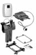
STEP #4
Sensor Mounting (select proper instructions based on sensor
type) |
|
In-Wall
Sensor (Requires the use of 1-3/4" hole saw bit.) |
|
1)
Determine hole location, check for obstructions behind the
wall, including wall studs, (image 17). After marking
location, drill 1-3/4" hole with hole saw into wall.
IMPORTANT: Center sensor eye 2-1/2" above seat in up
position (image 23).
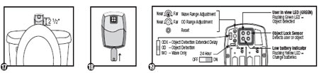
2) Unscrew cover using cover key (E) and remove sensor from
housing, (image 18).
3) Insert and fasten the sensor housing so that the
orientation of the mounting screws are horizontal, (images
19 & 20). Insert (4) AA batteries into sensor and reinstall
sensor into housing. Reattach the cover, (image 21). To
adjust sensor range see Step #5. |
|
 |
|
On-Wall
Sensor |
|
1) Center
sensor eye 2-1/2" above the seat in up position, (image 23).
Attach to wall using adhesive strip and/or screws & anchors
(G). Note the orientation of the sensor, (image 23).
WARNING: Adhesive strip can only be applied once; once
installed it is difficult to remove.
2) Remove cover using key, (image 24) and install (4) AA
batteries. Reattach sensor cover. To adjust sensor range see
Step #5. |
|
 |
|
|
|
STEP #5
Test Sensor Range/Adjustment |
|
Both
sensors are factory set. Green light on sensor will flash 3
times at the
start of every use. Should the sensor need adjusting:
1) Remove the cover using Cover Key (E), (image 18 or 24).
For On-Wall sensor, remove rubber cover concealing the reset
button and range adjuster screw.
2) Depress the sensor range reset button, (image 22 or 25).
During the 7 minute start up sequence the green light
flashes constantly when a user is in view.
3) Using the Sensor Tool (F), turn the sensor range
adjustment screw, (image 22 or 25) counter-clock wise,
shortening the sensor range, until the green light stops
flashing while you are standing at the front rim of the
bowl. Slowly turn the sensor range adjustment screw
clock-wise until the green light flashes while standing at
the front of the bowl.
4) Reinstall rubber cover for On-Wall sensor and re-attach
the cover.
<<BACK TO PAGE 1 |
|
|
Warning: Sloan Flushmate Systems do not retrofit the standard
gravity fed toilets |
| |
|
|
|
|
|
|
|
|
|
|